Description
Description:
The MEMS 16×16 Optical Switch Module (Model: MEMS-M-16X16-LC/APC) represents the pinnacle of modern optical switching technology. This device leverages MEMS (Micro-Electro-Mechanical Systems) technology to deliver precise and reliable optical path management. Designed for use in sophisticated optical networks, it offers superior performance characterized by low insertion loss, high return loss, and minimal crosstalk. Its compact and robust design ensures durability and ease of integration into a variety of network environments. With its advanced control interface, this switch module allows for both local and remote management, providing flexibility and enhanced operational capabilities. The MEMS-M-16X16-LC/APC is ideal for applications that require dynamic and efficient routing of optical signals, ensuring high-quality transmission and network stability.
Overview:
The MEMS 16×16 Optical Switch Module is an advanced optical device designed to facilitate dynamic reconfiguration of optical networks. It operates over a wide wavelength range (1310/1550 nm), providing minimal signal degradation with low insertion loss and high return loss. The module is equipped with 16 input and 16 output ports, which are controlled via an RS232 interface, making it compatible with a wide range of network infrastructures. Its compact dimensions (200 x 180 x 18 mm) and low power consumption (≤10W) make it suitable for space-constrained environments. The robust construction and advanced control features ensure reliable performance in various operational conditions, from laboratory settings to field deployments.
Applications:
- Optical Transmission Systems: Used for multi-channel optical monitoring, enabling efficient management of multiple optical paths within transmission systems.
- LAN Multi-Source/Detector Automatic Switching: Facilitates the automatic switching of multiple light sources and detectors, enhancing network flexibility and efficiency.
- Optical Sensing Systems: Applied in multi-point dynamic monitoring systems for real-time sensing and data collection.
- Optical Testing Systems: Utilized for testing optical fibers, optical devices, networks, and field engineering projects.
- Optical Device Assembly and Adjustment: Aids in the precise assembly and adjustment of various optical components, ensuring optimal performance.
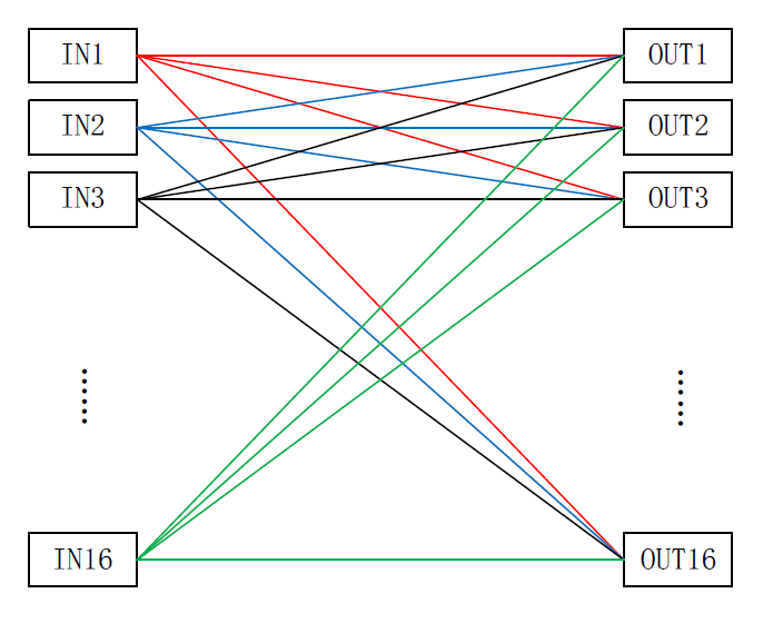
Optical Path Diagram:

Performance Specifications:
| Parameter | Unit | Specification |
|---|---|---|
| Model | – | MEMS-M-16X16-LC/APC |
| Operating Wavelength | nm | 1310/1550 |
| Insertion Loss | dB | ≤3.0 |
| Return Loss | dB | ≥45 |
| Crosstalk | dB | ≥50 |
| Switching Time | ms | ≤10 |
| Transmission Optical Power | dBm | ≤23 |
| Optical Fiber Type | – | SM-9/125 |
| Optical Interface Type | – | LC/APC |
| Output Fiber Length | m | 1.00 |
| Control Interface | – | RS232 |
| Operating Voltage | – | DC 5V |
| Power Consumption | W | ≤10 |
| Operating Temperature | ℃ | -5 to +70 |
| Storage Temperature | ℃ | -45 to +75 |
| Module Dimensions | mm | 200x180x18 |
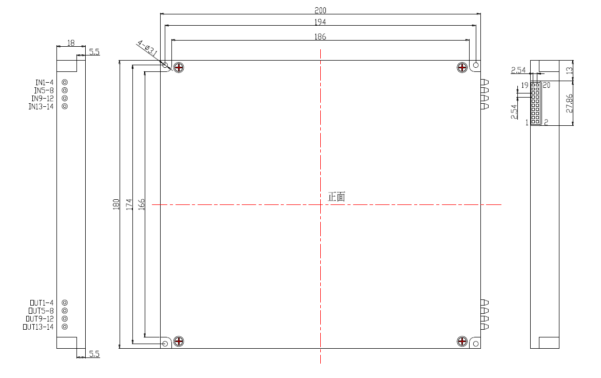
Dimension Diagram:
Pin Definition:
| Pin# | Signal Name | Type | Description |
|---|---|---|---|
| 1, 2 | VCC | Power | +5VDC, Digital power supply |
| 3, 4 | GND | Power | Digital ground |
| 5 | TXD | Output | Transmit Data |
| 6 | RXD | Input | Receive Data |
| 7, 8 | GND | Power | Digital ground |
| 9-20 | NC | – | Not Connected |
Program Control Command Description:
This device can receive control signals from a computer through the RS232 interface to achieve automatic measurement or real-time monitoring.
- Only one command can be executed at a time. Usually, the next command can be entered after the program returns the corresponding value.
- Please use uppercase letters.
- Use angle brackets “<” as the start symbol and “>” as the end symbol during actual operation.
- Command errors will return <ER>.
| Command | Description | Example |
|---|---|---|
| <OSW_SW_a_b_c_d_e_f_g_h_i_j_k_l_m_n_o_p> | Channel Switching | Send: <OSW_SW_In1 corresponding output channel_In2 corresponding output channel_In3 corresponding output channel_In4 corresponding output channel_In5 corresponding output channel_In6 corresponding output channel_In7 corresponding output channel_In8 corresponding output channel_In9 corresponding output channel_In10 corresponding output channel_In11 corresponding output channel_In12 corresponding output channel_In13 corresponding output channel_In14 corresponding output channel_In15 corresponding output channel_In16 corresponding output channel> Send: <OSW_SW_01_02_03_04_05_06_07_08_09_10_11_12_13_14_15_16> Return: <OSW_SW_01_02_03_04_05_06_07_08_09_10_11_12_13_14_15_16_OK> Represents setting the 16×16 optical path as: In1→Out1, In2→Out2, In3→Out3, In4→Out4, In5→Out5, In6→Out6, In7→Out7, In8→Out8, In9→Out9, In10→Out10, In11→Out11, In12→Out12, In13→Out13, In14→Out14, In15→Out15, In16→Out16. |
| <OSW_A_?> | Query Channel Status | Success Return: <OSW_A_In1 corresponding output channel_In2 corresponding output channel_In3 corresponding output channel_In4 corresponding output channel_In5 corresponding output channel_In6 corresponding output channel_In7 corresponding output channel_In8 corresponding output channel_In9 corresponding output channel_In10 corresponding output channel_In11 corresponding output channel_In12 corresponding output channel_In13 corresponding output channel_In14 corresponding output channel_In15 corresponding output channel_In16 corresponding output channel> Return: <OSW_A_01_02_03_04_05_06_07_08_09_10_11_12_13_14_15_16> Current optical path: In1→Out1, In2→Out2, In3→Out3, In4→Out4, In5→Out5, In6→Out6, In7→Out7, In8→Out8, In9→Out9, In10→Out10, In11→Out11, In12→Out12, In13→Out13, In14→Out14, In15→Out15, In16→Out16. |
| <OSW_BAUD_x> | Set or Query Baud Rate | 1. x is 1~9, representing baud rates of 2400, 4800, 9600, 14400, 19200, 38400, 56000, 57600, 115200 respectively. Success Return: <OSW_BAUD_x_OK> 2. Send <OSW_BAUD_?> to query baud rate. Send: <OSW_BAUD_5> Sets the device baud rate to 19200. Configuration takes effect after restart! |
| <INFO_?> | Query Device Information | Success Return: <MEMS-16x16_VER1.00_SN01234567890_C10.02.00025> Indicates MEMS 16×16 device, version 1.00, SN number 01234567890, product number C10.02.00025. |
| <SAVE_ALL> | Save Configuration | Success Return: <OK> Saves the configuration, such as channel status. |
Factory Default Configuration:
| Item | Factory Default Configuration | Remarks |
|---|---|---|
| Initial Power-on Channel | In1→Out1, In2→Out2, In3→Out3, In4→Out4, In5→Out5, In6→Out6, In7→Out7, In8→Out8, In9→Out9, In10→Out10, In11→Out11, In12→Out12, In13→Out13, In14→Out14, In15→Out15, In16→Out16 | The device maintains the optical path state saved before power off. |
| Serial Port Baud Rate | 115200 | 8 data bits, 1 stop bit, no parity. |


