Description
Description:
The D40×40 Matrix Optical Switch (Model: IOXC D40×40) is a high-capacity, intelligent optical cross-connect device designed to handle complex optical routing tasks in large-scale networks. This switch matrix allows for non-blocking bidirectional cross-connections of up to 40 input and 40 output channels, making it ideal for sophisticated optical communication systems. It features advanced optical switching technology that ensures low insertion loss, rapid switching speeds, and high signal stability. The D40×40 Matrix Optical Switch is housed in a robust 19-inch standard 3U chassis, ensuring compatibility with standard rack-mounted systems and providing a reliable solution for demanding network environments.
Overview:
The D40×40 Matrix Optical Switch is a versatile and robust solution for managing optical paths in large-scale communication networks. With 40 input and 40 output ports, it is designed to enable seamless and flexible routing of optical signals. The switch operates at an 850 nm wavelength and is equipped with LC/UPC optical interfaces. It supports both local and remote control through serial and network interfaces, making it suitable for diverse deployment scenarios. The device’s design ensures minimal signal disruption and high performance, with low insertion loss, high return loss, and excellent crosstalk isolation. Its advanced control capabilities and durable construction make it a preferred choice for complex optical network management.
Applications:
- Multi-Channel Optical Monitoring: Used in optical transmission systems for monitoring multiple optical channels simultaneously.
- LAN Multi-Source/Detector Automatic Switching: Facilitates the automatic switching of multiple light sources and detectors, enhancing network adaptability and efficiency.
- Dynamic Monitoring in Optical Sensing Systems: Applied in systems requiring real-time optical sensing and data collection.
- Optical Fiber and Device Testing Systems: Utilized for testing and validating the performance of optical fibers, devices, networks, and field engineering projects.
- Assembly and Adjustment of Optical Devices: Assists in the precise assembly and fine-tuning of optical components, ensuring optimal performance and reliability.
Product Features:
- Strictly non-blocking bidirectional cross-connection.
- Low insertion loss, fast switching speed, and high signal stability.
- Supports channel switching and status query via remote client access, enabling human-machine interaction.
- Allows both local and remote control.
Performance Specifications:
| Parameter | Unit | Specification |
|---|---|---|
| Model | – | IOXC D40×40 |
| Operating Wavelength | nm | MM 850 |
| Optical Interface | – | LC/UPC |
| Insertion Loss (1) | dB | <2.5 |
| Polarization Loss | dB | 0.1 |
| Crosstalk | dB | 55 |
| Return Loss | dB | 45 |
| Wavelength Dependent Loss | dB | 0.3 (C+L Band) |
| Repeatability (2) | dB | ±0.05 |
| Switching Time | ms | <20 |
| Maximum Input Optical Power | dBm | 27 |
| Switching Life | cycles | 10^9 |
| Operating Power | – | AC 220 V (50Hz) |
| Operating Temperature | ℃ | +5℃ to +45℃, Humidity <85% |
| Storage Temperature | ℃ | -40℃ to +70℃, Humidity <40% |
| Control Interface | – | Serial: 19200bps; Network: 10/100M |
| Chassis Structure | – | 19-inch standard 3U (483×350×132) |
Factory Settings:
- Serial port settings: 19200 baud rate, 8 data bits, 1 stop bit, no parity.
- IP address: 192.168.1.136; Operating mode: TCP Server; Operating port: 4001. (Note: Except for special user requirements.)
User Instructions:
Front Panel Description:

- Optical Input Ports – 40 in optical input ports.
- Optical Output Ports – 40 out optical output ports.
- Power Indicator – Green light. Lights up when power is on.
- LCD Display.
- Operation Buttons.
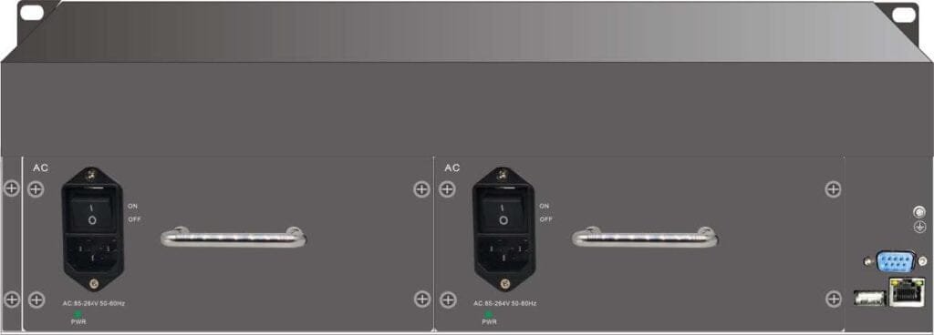
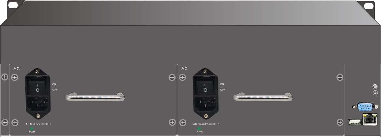
Rear Panel Description:

- LAN – Ethernet interface, RJ45 socket. Used when the host communicates with the device via Ethernet.
- RS232 – RS232 interface, DB9 pin socket. Used when the host communicates with the device via RS232 serial port.
- AC220 – Power socket providing AC220V power interface.
- POWER – Power switch, “on” is power on, “off” is power off.
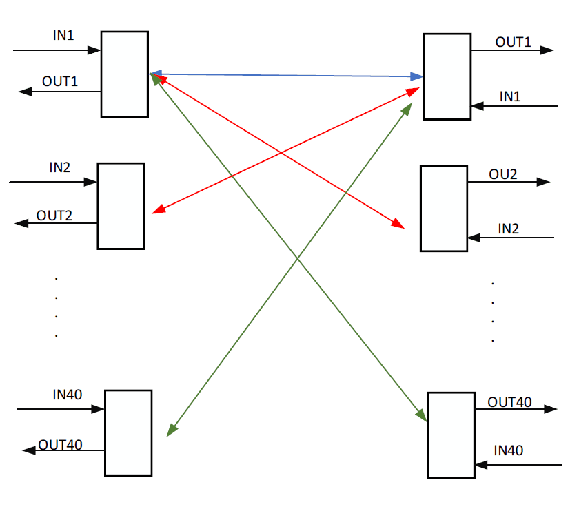
Optical Path Connection Illustration:

Communication Interface Connection Instructions
- RS-232 Interface When connecting the device to a computer, a DB9 female-to-female crossover cable should be used. Pin #2 and #3 are crossed, and pin #5 is connected directly. Other pins are not connected.
- RJ45 Ethernet Interface When connecting the device to a computer through a switch, use a straight-through cable (both ends in the order: 1-orange white, 2-orange, 3-green white, 4-blue, 5-blue white, 6-green, 7-brown white, 8-brown). When connecting the device directly to a computer, use a crossover cable (one end in the order: 1-orange white, 2-orange, 3-green white, 4-blue, 5-blue white, 6-green, 7-brown white, 8-brown; the other end in the order: 1-green white, 2-green, 3-orange white, 4-blue, 5-blue white, 6-orange, 7-brown white, 8-brown).


